EMW-200
INFOThe differences between the EMW-200 and the EML-200 The Master Oscillator
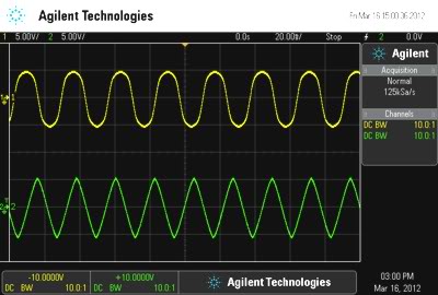
The Master Oscillator on the EMW-200 uses the same core circuit used on the EML-200, however we made a few improvements. One was made in the sine wave waveshaper circuit, we modified it in order to produce a more precise sine waveform, as seen on the above image. Another improvement was the replacement of the less reliable mechanical rotary switch with a digital controlled mechanical micro relay system, this way the range adjustment could use a normal potentiometer, what guarantees future replacements if necessary. Note that only the control circuit is digital, the signal path on the entire module is completely analog. The Voltage Controlled Oscillators
The Voltage Controlled Oscillators on both machines, the EMW-200 and the EML-200 uses the same transistor type VCO, we only made minor changes in order to improve the frequency range. On the EML-200 the circuit starts operating at aproximately 10Hz and stops at 10KHz. On the EMW-200 the VCO range goes from 1Hz to 17KHz. The Delay module
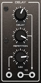
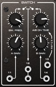
The Delay module on the EMW-200 uses a special design that emulates a vintage echo chamber, it is very usefull and has controls for the Delay Time, Repetition (regeneration) and Effect Mix. A demonstration video below shows the Delay module in operation. The Switch module
The Filters
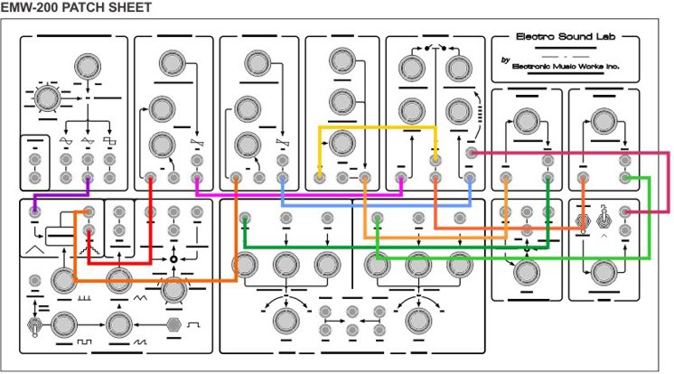
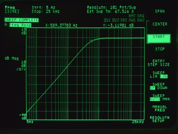
There are two filters on the EMW-200 and they are of the exact same type found on the EML-200, one is a Highpass and the other is a Lowpass filter, both are 6db/oct. These filters give a very characteristic tone to the synthesizer sound, almost like an effect that dips things into a dark or misty athmosphere. They are not usual filters as we are used to see, they are simple and have unusual characteristics, but their simplicity turns out to be a powerfull feature and at some extend gives to this machine its sound personality. Below is a little demo video that exemplifies and shows the two filters in action. On the next video you will be able to hear the two filters being used on a more complex patch. Here is the patch sheet for this FILTER FUN patch:
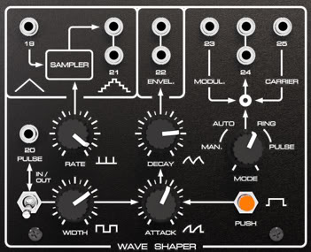
Description: The Wave Shaper module
The Wave Shaper on the EMW-200 is a module composed of 4 submodules, a sample & hold (SAMPLER), an oscillator with pulse width control, an A/D (Attack/Decay) generator and a Ring Modulator. Beyond that there is a switching system that selects 4 ways to feed the modulation input of the ring modulator module and a manual trigger for the attack/decay generator.
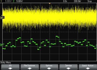
The Sample & Hold can be fed by any waveform on the EMW-200, including the Noise source from the Master Oscillator module. The following demo video shows how the Sample & Hold operates and its effect on a triangular waveform and on the noise source. In order to hear the Sample & Hold effect we connect its output to the VCO n.1 modulation input. The Oscillator submodule
The Ring Modulator submodule The Mixer
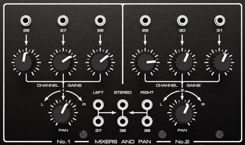
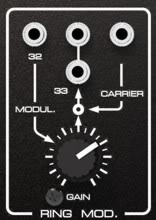
The Mixer on the EMW-200 is an exact replica of EML-200 mixer, it is a very flexible and well planed module. It has two sections of three channels each that can be addresses to L (Left), R (Right) and Stereo output jacks, this allow us to create very dinamic stereo images where separated sound elements can appear and/or move within the stereo field. The Ring Modulator module
The Ring Modulator mixes two signals on a special way, it uses the MODULATOR signal to alter the CARRIER signal amplitude. With low frequency signals it can be used as a VCA, where 0 Volts do not allow any Carrier signal appearing on the Output. Here is a video that uses the VCO No.1 signal as a modulator for the square wave from the Master Oscillator. The LFO module
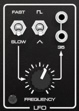
As explained at the begining of this page, on the EMW-200 the MIC AMP. module present on the EML-200 was replaced with a LFO. It provides the equipment with more useful resources to alter and modulate the sounds. The LFO has a RANGE switch (SLOW / FAST), two selectable waveforms (SQUARE / TRIANGLE), a potentiometer to control the Frequency and two outputs. Technical Specifications Dimensions and Weight
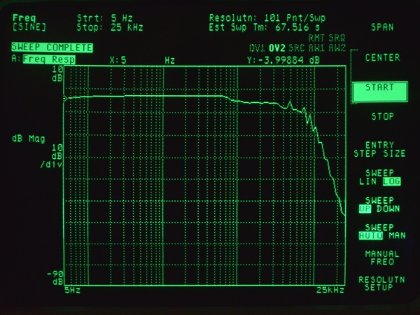
Frequency response curve (Direct signal):
Switch
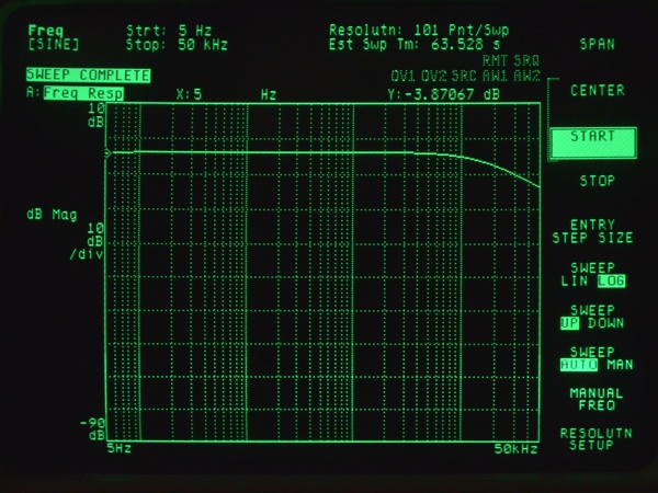
High Pass Filter
Wave Shaper |